


 الفيزياء الكلاسيكية
 الكهربائية والمغناطيسية
 علم البصريات
 الفيزياء الحديثة
 النظرية النسبية
 الفيزياء النووية
 فيزياء الحالة الصلبة
 الليزر
 علم الفلك
 المجموعة الشمسية
 الطاقة البديلة
 الفيزياء والعلوم الأخرى
 مواضيع عامة في الفيزياء
|
Read More
Date: 31-1-2021
Date: 27-1-2021
Date: 9-3-2016
|
RESONATOR ALIGNMENT: A PRACTICAL APPROACH
The alignment of cavity optics can be done using a number of methods, depending on the laser specifically on the diameter of the laser gain medium itself. When the laser undergoing alignment has a large bore, such as a carbon dioxide laser (which frequently have tube diameters of 10 mm or more) or a YAG laser (with diameters typically ranging from 4 to 8 mm), the simplest method often involves the use of a small visible alignment laser, such as a HeNe or red diode laser. The alignment process begins by removing the OC and aligning the beam from the HeNe laser such that it enters the front of the laser, passes through the gain medium, reflecting off the HR back through the gain medium, and exiting the laser. When a card with a small hole in it is placed in front of a HeNe laser, the HR is easily aligned such that the beam reflected from the HR and exiting the laser is parallel to the beam entering the laser (literally, “on top” of it). Visually, the mirror is aligned when the reflected and original beams become one. The OC may now be replaced and aligned in a similar manner, but in this case there will be a plethora of reflections since some rays will reflect from the OC, striking the HR, and then exit to be seen on the card as shown in Figure 1.1. Still, it is usually easy to identify the first reflection from the OC (it is the second brightest spot) and to align it so that all spots on the card converge to a single spot. At that point, almost by definition, the mirrors are parallel.
This technique works only for lasers where the visible alignment beam can pass through the cavity optics. In most cases it works well with YAG lasers, since the mirrors often have high transmission at the HeNe wavelength of 632.8 nm. This is because it is common with high-power lasers such as YAG to use a small HeNe laser as a coaxial targeting laser in which the red HeNe beam emerges from the laser to identify where the target will be hit when the YAG is energized. In many cases, CO2 laser optics allow alignment by the same method (e.g., while the HR in many CO2 lasers is made of germanium, which does not pass visible light, the output couplers of many lasers are made of ZnSe, which reflects about 60 to 70% at 10.6 μm and is also partially transmitting at the red wavelength of the HeNe laser).
For small-bore lasers such as HeNe and argon lasers (where the inside diameter of the plasma tube is 1 mm or less), the alignment of an external laser beam down the bore is very difficult. In many cases it is difficult to distinguish total internal reflection (from the almost parallel angle of the alignment laser) from the alignment beam itself, so an autocollimator is often used. The autocollimator produces a beam of collimated light (i.e., light with parallel rays), which is then directed through the laser tube, reflected from the cavity mirror at the far end, and back through the tube to be seen by the observer. An incandescent lamp is used as a light source, and when the mirror is aligned properly, the observer will see an image of the filament. The configuration is shown in Figure 1.2, and a photograph of the image of the filament as seen reflected from the mirror being aligned is shown in Figure 1.3. The next step in the alignment procedure is to align the OC. This may be accomplished by using the autocollimator by removing the (just aligned) HR, installing the OC, and aligning it separately in a manner similar to that used for the HR. The

Figure 1.1. Alignment using a small HeNe laser.

Figure 1.2. Alignment using an autocollimator.
location of the autocollimator is simply changed to the rear of the laser. The alternative is a simple search procedure in which the mirror is rocked with the laser energized until aligned. To perform the search pattern, the OC is installed and is aligned so that the reflected beam falls to one side of the tube. The mirror is now rocked in an up–down motion while the mirror is scanned slowly from one side to the other as shown in Figure 1.4. As the search pattern progresses with the mirror scanning up and down and side to side, a blink of laser light will be observed. At this point the mirror is aligned in the horizontal (sideways) direction. The adjusting screw for the vertical axis is now adjusted until a continuous beam appears.
Finally, both the OC and HR mirrors are adjusted for maximum output. More specifically, the mirrors are “tweaked” to ensure that they are parallel. It is quite likely that upon first alignment the mirrors are not perfectly perpendicular to the tube, as shown in the top diagram of Figure 1.5, in which the path of the intracavity beam is shaded. In this situation the mirrors are parallel to each other, with a clear path through the gain medium allowing oscillation. However, the utilization of the volume of the gain medium is poor, so power output will be much lower than when the mirrors are fully optimized and perpendicular to the tube, so that the entire volume of the laser tube is used as depicted in the lower diagram of the figure. By
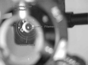
Figure 1.3. View of the filament image through the autocollimator.
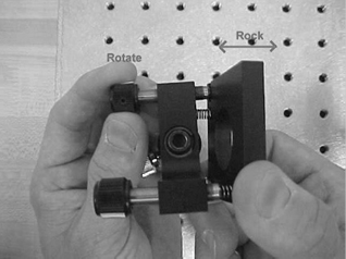
Figure 1.4. Rocking procedure to align the OC.
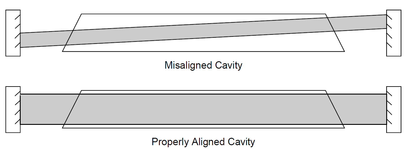
Figure 1.5. Possible misalignment of the mirrors.
adjusting the mirrors carefully in both directions by “rocking” the screws in either direction, one may optimize the setup for maximum power output.

|
|
|
|
علامات بسيطة في جسدك قد تنذر بمرض "قاتل"
|
|
|
|
|
|
|
أول صور ثلاثية الأبعاد للغدة الزعترية البشرية
|
|
|
|
|
|
|
مدرسة دار العلم.. صرح علميّ متميز في كربلاء لنشر علوم أهل البيت (عليهم السلام)
|
|
|