


 تاريخ الرياضيات
 الرياضيات في الحضارات المختلفة
 الرياضيات المتقطعة
 الجبر
الجبر
 الهندسة
 المعادلات التفاضلية و التكاملية
 التحليل
 علماء الرياضيات
 |
Read More
Date: 3-1-2017
Date: 1-1-2017
Date: 4-1-2017
|
There are several common methods by which computers add numbers. One thing peculiar to all computers is that numbers are added in pairs only. If a sum of three numbers is required, two numbers are summed first and the third is then added to the sum. In the following discussion, then, we will consider only the problem of adding two numbers. Methods for addition may be classified as either parallel or serial methods. The difference in method is determined by the way in which the numbers are transmitted or fed into the computer.
In parallel methods, a number is given by signals (or lack of them) carried by a set of leads, one for each digit of the number. The number 101, for instance, would be represented by three leads, the first and third of which would carry a signal (positive voltage) and the second of which would carry no signal. Parallel methods of addition will add two numbers by considering all positions in the numbers at once and producing on a third set of leads signals which correspond to the sum.
In serial methods, numbers are transmitted to the machine one digit at a time, beginning with the digit in lowest position. As the sequence of signals is fed into the adding device, the digits are combined progressively and the sum is given as a sequential output.
Concerning these two basic methods, one can say that the parallel method requires somewhat more apparatus, whereas the serial method requires a somewhat longer time. This distinction is by no means clearcut, and the saving in time, or conversely in equipment, depends on many factors. It has not been shown that either method is definitely the better in any general sense. As a result, both methods are being used. We will discuss a method of parallel addition only. The interested student can find a description of other methods in the texts listed at the end of this chapter.
In combining two digits in any radix, whenever the sum exceeds or equals the radix, it is necessary to "carry" a digit into the next position to the left. This means that in adding two numbers of several digits, there will be times when in a given position we will actually need to add three digits. In fact, except for the rightmost digit, this will always be the case since we will always consider a carry digit which may be either 0 or 1 in the binary system. Because of this carry, it is convenient to perform additions in two steps. The first step will be performed by a new logical circuit element which we will term a half adder. The half adder will be a device capable of performing the operation indicated by Table 1-1. That
TABLE 1-1
ADDITION OF BINARY NUMBERS

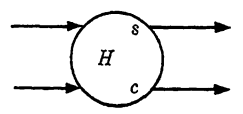
FIG. 1-1. Symbolic noation for a half adder.
is, the half adder will have two inputs, corresponding to the two addends, and it will have two outputs, one giving the sum digit and the other giving the carry digit, as indicated in the table. The symbol to be used in future circuit diagrams is shown in Fig. 6-6. The lower case letters s and c are used to distinguish between the two outputs.
A circuit for the half adder can be derived readily by considering the sum and carry outputs separately as functions of the inputs. Suppose that we call the inputs x and y; then it is clear that the function for the sum may be written as s = xy' + x'y since 1 appears as the sum if and only if one, but not both, of the addends is 1. Similarly, the function for the carry is given by c = xy. Interpreting these functions directly in terms of logical elements, we have one circuit for a half adder as shown in Fig. 1-2. Other circuits are suggested in the exercises.
With the half adder of Fig. 1-2 as a component, it is not difficult to build a circuit for parallel addition of two binary numbers. Let us assume for simplicity that the two numbers are each 3-digit (or less), represented by
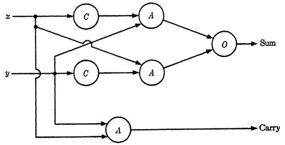
FIG. 1-2. Logical circuit for a half adder.
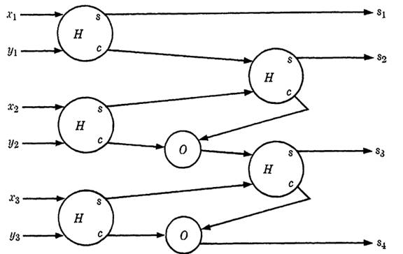
FIG. 1-3. Circuit for the addition of two 3-digit numbers.
X = x3x2x1 and Y = y3y2y1, where each x1 and y; is either 0 or 1. These digits are supplied in pairs to half adders as shown in Fig. 1-3. The sum (answer) is the number 84838281i given by the four outputs. That this circuit will work is self-evident. After the first position, the circuit is the same for each higher position. Two inputs, say x2 and y2, are combined in a half adder, with the sum going to a second half adder to be combined with a carry from position 1. The sum of half adder 2 is the second digit of the answer, and the carry from the two half adders are combined with an "or" element to give the carry for the next higher position. Note that these two half adders cannot both yield a carry signal, since if the first showed 1 as a carry it must have 0 as a sum and hence the second half adder cannot also have a carry. If more than three digits are being added, the bottom output becomes the carry to the fourth position rather than the fourth digit of the answer.
|
|
|
|
تفوقت في الاختبار على الجميع.. فاكهة "خارقة" في عالم التغذية
|
|
|
|
|
|
|
أمين عام أوبك: النفط الخام والغاز الطبيعي "هبة من الله"
|
|
|
|
|
|
|
قسم شؤون المعارف ينظم دورة عن آليات عمل الفهارس الفنية للموسوعات والكتب لملاكاته
|
|
|