

 علم الكيمياء
 الكيمياء التحليلية
 الكيمياء الحياتية
 الكيمياء العضوية
 الكيمياء الفيزيائية
 الكيمياء اللاعضوية
 مواضيع اخرى في الكيمياء
 الكيمياء الصناعية
 |
Read More
Date: 30-7-2017
Date: 29-8-2017
Date: 10-8-2017
|
ATMOSPHERIC DISTILLATION
Atmospheric distillation separates the crude oil complex mixture into different fractions with relatively narrow boiling ranges. In general, separation of a mixture into fractions is based primarily on the difference in the boiling points of the components. In atmospheric distillation units, one or more fractionating columns are used. Distilling a crude oil starts by preheating the feed by exchange with the hot product streams. The feed is further heated to about 320°C as it passes through the heater pipe (pipe still heater).
The hot feed enters the fractionator, which normally contains 30–50 fractionation trays. Steam is introduced at the bottom of the fractionator to strip off light components. The efficiency of separation is a function of the number of theoretical plates of the fractionating tower and the reflux ratio. Reflux is provided by condensing part of the tower overhead vapors. Reflux ratio is the ratio of vapors condensing back to the still to vapors condensing out of the still (distillate). The higher the reflux ratio, the better the separation of the mixture. Products are withdrawn from the distillation tower as side streams, while the reflux is provided by returning a portion of the cooled vapors from the tower overhead condenser.
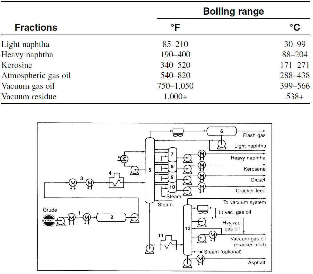
Additional reflux could be obtained by returning part of the cold side stream products to the tower. In practice, the reflux ratio varies over a wide range according to the specific separations desired. From the overhead condenser, the uncondensed gases are separated, and the condensed light naphtha liquid is withdrawn to storage. Heavy naphtha, kerosine, and gas oil are withdrawn as side stream products. Table 1-1 shows the approximate boiling ranges for crude oil fractions. The residue (topped crude) is removed from the bottom of the distillation tower and may be used as a fuel oil. It may also be charged to a vacuum distillation unit, a catalytic cracking or steam cracking process. Figure 1-1 is a flow diagram for atmospheric and vacuum distillation units.
Table 1-1 Approximate ASTM boiling point ranges for crude oil fractions

Figure 1-1. Flow diagram of atmospheric and vacuum distillation units:1 (1,3) heat exchangers; (2) desalter, (3,4) heater; (5) distillation column, (6) overhead condenser, (7–10) pump around streams, (11) vacuum distillation heater; (12) vacuum tower.


|
|
|
|
علامات بسيطة في جسدك قد تنذر بمرض "قاتل"
|
|
|
|
|
|
|
أول صور ثلاثية الأبعاد للغدة الزعترية البشرية
|
|
|
|
|
|
|
مدرسة دار العلم.. صرح علميّ متميز في كربلاء لنشر علوم أهل البيت (عليهم السلام)
|
|
|