

 الفيزياء الكلاسيكية
 الكهربائية والمغناطيسية
 علم البصريات
 الفيزياء الحديثة
 النظرية النسبية
 الفيزياء النووية
 فيزياء الحالة الصلبة
 الليزر
 علم الفلك
 المجموعة الشمسية
 الطاقة البديلة
 الفيزياء والعلوم الأخرى
 مواضيع عامة في الفيزياء
|
Read More
Date: 22-1-2021
Date: 22-12-2016
Date: 18-4-2016
|
Electro-Optical Q-Switches
Very fast electronically controlled optical shutters can be designed by exploiting the electro-optic effect in crystals or liquids. The key element in such a shutter is an electro-optic element that becomes birefringent under the influence of an external field. Birefringence in a medium is characterized by two orthogonal directions, called the “fast” and “slow” axes, which have different indices of refraction.
An optical beam, initially plane-polarized at 45◦ to these axes and directed normal to their plane, will split into two orthogonal components, traveling along the same path but at different velocities. Hence, the electro-optic effect causes a phase difference between the two beams. After traversing the medium, the combination of the two components results, depending on the voltage applied, in either an elliptical, circular, or linearly polarized beam. For Q-switch operation only two particular voltages leading to a quarter-wave and half-wave retardation are of interest. In the first case, the incident linearly polarized light is circular polarized after passing the cell, and in the second case the output beam is linearly polarized; however, the plane of polarization has been rotated 90◦.
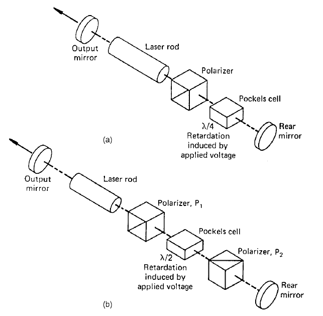
The two most common arrangements for Q-switching are shown in Fig. 1. In Fig. 1(a) the electro-optic cell is located between a polarizer and the rear mirror.

FIGURE 1. Electro-optic Q-switch operated at (a) quarter-wave and (b) half-wave retardation voltage.
The inclusion of the polarizer is not essential if the laser radiation is polarized, such as, for example, in Nd : YLF. The sequence of operation is as follows: During the flashlamp pulse, a voltage V1/4 is applied to the electro-optic cell such that the linearly polarized light passed through the polarizer is circularly polarized. After being reflected at the mirror, the radiation again passes through the electro-optic cell and undergoes another λ/4 retardation, becoming linearly polarized but at 90◦ to its original direction. This radiation is ejected from the laser cavity by the polarizer, thus preventing optical feedback. Toward the end of the flashlamp pulse the voltage on the cell is switched off, permitting the polarizer–cell combination to pass a linearly polarized beam without loss. Oscillation within the cavity will build up, and after a short delay a Q-switch pulse will be emitted from the cavity. In the arrangement of Fig. 1(b) an electric voltage must first be applied to the cell to transmit the beam. In this so-called pulse-on Q-switch, the cell is located between two crossed polarizers. As before, polarizer P1, located between the laser rod and the cell, is not required if the active medium emits a polarized beam. During the flashlamp pulse, with no voltage applied to the cell, the cavity Q is at a minimum due to the crossed polarizers. At the end of the pump pulse a voltage V1/2 is applied to the cell, which causes a 90◦ rotation of the incoming beam. The light is therefore transmitted by the second polarizer P2. Upon reflection at the mirror the light passes again through polarizer P2 and the cell, where it experiences another 90◦ rotation. Light traveling toward the polarizer P1 has experienced a 180◦ rotation and is therefore transmitted through P1.
Two types of electro-optic effects have been utilized in laser Q-switches: the Pockels effect, which occurs in crystals that lack a center of point symmetry, and the Kerr effect, which occurs in certain liquids. Pockels cells, which require a factor of 5 to 10 lower voltage than Kerr cells, are the most widely used active devices for Q-switching pulsed lasers.


|
|
|
|
علامات بسيطة في جسدك قد تنذر بمرض "قاتل"
|
|
|
|
|
|
|
أول صور ثلاثية الأبعاد للغدة الزعترية البشرية
|
|
|
|
|
|
|
مدرسة دار العلم.. صرح علميّ متميز في كربلاء لنشر علوم أهل البيت (عليهم السلام)
|
|
|