

 الفيزياء الكلاسيكية
 الكهربائية والمغناطيسية
 علم البصريات
 الفيزياء الحديثة
 النظرية النسبية
 الفيزياء النووية
 فيزياء الحالة الصلبة
 الليزر
 علم الفلك
 المجموعة الشمسية
 الطاقة البديلة
 الفيزياء والعلوم الأخرى
 مواضيع عامة في الفيزياء
|
Read More
Date: 3-1-2021
Date: 9-11-2020
Date: 21-3-2016
|
Modes in a confocal resonator
This resonator is formed by two spherical mirrors of equal curvature separated by their common radius of curvature. The focal length of a mirror is one half of its radius of curvature, so that the focal points of the reflectors coincide. The reflectors are assumed to be square with the edge length 2A (compare fig. 1.1), which is small compared to the spacing D = R where R is the radius. A and R are large compared to the wave-length. Because of the symmetry of the problem we can choose the electric field vector either in x or y direction. In the following we shall drop that index x or y. Actually

Fig. 1.1. Confocal resonator with mirrors S and S'. The coordinates used in the text are indicated.
all the essential steps of the mathematical analysis can be seen when we deal with a scalar field using Huygens' principle. Let the field strength at point x' be given by E(x'). Then according to Huygens' principle this point is a starting point of a new spherical wave which produces a field strength at point x which is given by
 (1.1)
(1.1)
Here k is the wave number; x and x' are vectors defined by
 (1.2)
(1.2)
 (1.3)
(1.3)
The total field at point x is found by integrating over all original points x' on a surface. In the following we shall consider the spherical mirrors as such a surface and we shall choose the coordinates x and y on them. Corresponding to the two mirrors S and S' we write
 (1.4)
(1.4)
and
 (1.5)
(1.5)
The field on mirror S is given by
 (1.6)
(1.6)
where
 (1.7)
(1.7)
Because of 2A < R we approximate p by
 (1.8)
(1.8)
In accordance to what we define a mode by the property that its field distribution is repeated when going from one mirror to the other one, besides a constant factor σ,
 (1.9)
(1.9)
Inserting (1.6) into (1.9) we find an equation for Es'. To solve this equation we proceed in several simple steps. Because it will turn out in a self-consistent fashion that the spot-size of the field distribution is much smaller than R we make the following approximation:
 (1.10)
But when we insert (1.10) into the r.h.s. of (1.6) we may factorize the integral into one referring to xx' and one referring to yy'. This suggests to make the following hypothesis in the form of a product:
 (1.11)
where E0 is a constant. For formal reasons we decompose also σ into a product:
 (1.12)
Inserting (1.11) and (1.12) into (1.9), where we have used (1.6) and (1.10), we find
 (1.13)
Because on each of both sides there is a product of a function of x and one of y this equation can be fulfilled only if the factors fulfil the following equation:
 (1.14)
and a corresponding equation for g(x). Eq. (3.14) is called an integral equation and it has been solved exactly. The solutions are given by the angular wave functions in prolate spherical coordinates as defined by Flammer. But probably hardly anybody is familiar with this kind of wave functions. Fortunately, for our purposes the solution of (1.14) can be written in a very familiar form provided the field has not too many nodes in the x, y plane. In such a case it is well concentrated around the axis so that x/A << 1. If the field is strongly concentrated, the contributions of the integral in the region of x' ≈ ± A are practically negligible and we can extend the limits of the integral to infinity. Therefore instead of (1.14) we now have to solve
 (1.15)
After a little bit of guessing one may quite easily find the solution of the equation (1.15). It is nothing but a Gaussian distribution
 (1.16)
We leave it as a little exercise to the reader to check that (1.16) is indeed a solution of (1.15) and to determine the constant in front of the integral. In the following it will be convenient to have a suitable abbreviation, namely
 (1.17)
With (1.16) and (1.17) and choosing the same solution for given y we find the field distribution on the mirrors. It is a Gaussian distribution
 (1.18)
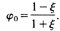
We may define the spot radius, w,, by that radius where (1.18) has dropped to l/e, whieh yields
 (1.19)
Huygens' principle allows one also to calculate the field inside the resonator. Because the derivation of the result is of a more technical nature we just write down the corresponding formulas. We use the abbreviation
 (1.20)
and find
 (1.21)
where
 (1.22)
and
 (1.23)
As we may see, in x, y-direction the field is still Gaussian though the spot size varies along the laser axis. The function sin φ looks rather complicated but a little analysis reveals that it has the following structure:
 (1.24)
where sin(kz) describes the fast oscillations of the field, whereas f(z) is a slowly varying function. That means that in z-direction, i.e. in the direction of the laser axis, the field mode strongly resembles that of a mode in a closed cavity. The field outside the cavity can also be found by means of Huygens' principle and reads
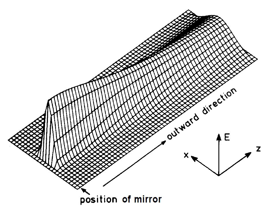
 (1.25)
where ct is the transmissivity of the mirrors. The far field pattern has a spot size which at a distance z is given by
 (1.26)
The angular beam width Θ can be defined as the ratio ws/z for z →∞ which yields
 (1.27)
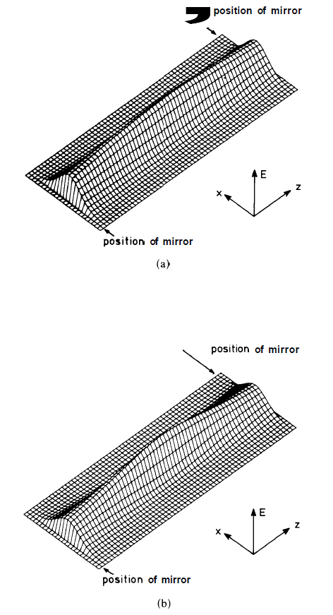
The results are represented in figs. 1.2 and 1.3. The field distribution (1.18) represents just the mode which has the lowest losses. A closer analysis shows that the whole sequence of modes is again of a form quite familiar to physicists. Namely, the general solution of (1.13) can be written as
 (1.28)
where Hm are the Hermitian polynomials, m = 0, 1,2, . . . and

at least in the case in which the Fresnel number N = ( 1/ 2π ) ( A2 k/ R)→ ∞. For sake of completeness we represent also the field inside and outside the resonator in the general case. The field outside the resonator is
 (1.29)
To obtain the field inside the resonator, the factor c, must be omitted and exp[-iφ(X, Y)] be replaced by sin(φ(X, Y)). In order to calculate the losses by diffraction, the finite size of the mirrors is, of course, crucial. The analysis shows, however, that the losses due to diffraction are in

Fig. 1.2. (a) Field distribution between two confocal mirrors, according to eq. (1.21). (a) and (b) show only the envelope. The rapidly oscillating function sin φ has been omitted. (b) In order to bring out the narrowing of the field distribution, in the middle part the field distribution of (a) is somewhat exaggerated.

Fig. 1.3. Field distribution outside the confocal resonator, according to eq. (1.25). In this figure only the envelope is shown. The rapidly oscillating function exp [iφ] has been omitted.
general much smaller, typically by a factor of 100, than losses due to the finite transmissivity of the mirrors. Therefore we shall not be concerned with these kinds of losses. We mention that in z-direction only discrete values of k are admitted which are given by
 (1.30)
where m, n and l are integers.


|
|
|
|
دراسة يابانية لتقليل مخاطر أمراض المواليد منخفضي الوزن
|
|
|
|
|
|
|
اكتشاف أكبر مرجان في العالم قبالة سواحل جزر سليمان
|
|
|
|
|
|
|
اتحاد كليات الطب الملكية البريطانية يشيد بالمستوى العلمي لطلبة جامعة العميد وبيئتها التعليمية
|
|
|