
آخر المواضيع المضافة

 الفيزياء الكلاسيكية
الكهربائية والمغناطيسية
علم البصريات
الفيزياء الحديثة
النظرية النسبية
الفيزياء النووية
فيزياء الحالة الصلبة
الليزر
علم الفلك
المجموعة الشمسية
الطاقة البديلة
الفيزياء والعلوم الأخرى
مواضيع عامة في الفيزياء
الفيزياء الكلاسيكية
الكهربائية والمغناطيسية
علم البصريات
الفيزياء الحديثة
النظرية النسبية
الفيزياء النووية
فيزياء الحالة الصلبة
الليزر
علم الفلك
المجموعة الشمسية
الطاقة البديلة
الفيزياء والعلوم الأخرى
مواضيع عامة في الفيزياء| Common-collector circuit |


|
|
Read More
Date: 20-4-2021
Date: 28-4-2021
Date: 28-4-2021
|
Common-collector circuit
A common-collector circuit (Fig. 1) operates with the collector at signal ground. The input is applied at the base just as it is with the common-emitter circuit.
The signal passes through C2 onto the base of the transistor. Resistors R2 and R3 provide the correct bias for the base. Resistor R4 limits the current through the transistor. Capacitor C3 keeps the collector at signal ground. A fluctuating direct current flows through R1, and a fluctuating dc voltage therefore appears across it. The ac part of this voltage passes through C1 to the output. Because the output follows the emitter current, this circuit is sometimes called an emitter follower circuit.
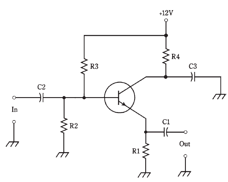
Fig. 1: Common-collector circuit configuration. This arrangement is also known as an emitter follower.
The output of this circuit is in phase with the input. The input impedance is high, and the output impedance is low. For this reason, the common-collector circuit can be used to match high impedances to low impedances. When well designed, an emitter follower works over a wide range of frequencies, and is a low-cost alternative to a broadband impedance-matching transformer.


|
|
|
|
"إنقاص الوزن".. مشروب تقليدي قد يتفوق على حقن "أوزيمبيك"
|
|
|
|
|
|
|
الصين تحقق اختراقا بطائرة مسيرة مزودة بالذكاء الاصطناعي
|
|
|
|
|
|
|
العتبة العباسية المقدسة تطلق النسخة الحادية عشرة من مسابقة الجود العالمية للقصيدة العمودية
|
|
|


