
تاريخ الرياضيات

الاعداد و نظريتها

تاريخ التحليل

تار يخ الجبر

الهندسة و التبلوجي


الرياضيات في الحضارات المختلفة

العربية

اليونانية

البابلية

الصينية

المايا

المصرية

الهندية


الرياضيات المتقطعة

المنطق

اسس الرياضيات

فلسفة الرياضيات

مواضيع عامة في المنطق


الجبر

الجبر الخطي

الجبر المجرد

الجبر البولياني

مواضيع عامة في الجبر

الضبابية

نظرية المجموعات

نظرية الزمر

نظرية الحلقات والحقول

نظرية الاعداد

نظرية الفئات

حساب المتجهات

المتتاليات-المتسلسلات

المصفوفات و نظريتها

المثلثات


الهندسة

الهندسة المستوية

الهندسة غير المستوية

مواضيع عامة في الهندسة

التفاضل و التكامل


المعادلات التفاضلية و التكاملية

معادلات تفاضلية

معادلات تكاملية

مواضيع عامة في المعادلات


التحليل

التحليل العددي

التحليل العقدي

التحليل الدالي

مواضيع عامة في التحليل

التحليل الحقيقي

التبلوجيا

نظرية الالعاب

الاحتمالات و الاحصاء

نظرية التحكم

بحوث العمليات

نظرية الكم

الشفرات

الرياضيات التطبيقية

نظريات ومبرهنات


علماء الرياضيات

500AD

500-1499

1000to1499

1500to1599

1600to1649

1650to1699

1700to1749

1750to1779

1780to1799

1800to1819

1820to1829

1830to1839

1840to1849

1850to1859

1860to1864

1865to1869

1870to1874

1875to1879

1880to1884

1885to1889

1890to1894

1895to1899

1900to1904

1905to1909

1910to1914

1915to1919

1920to1924

1925to1929

1930to1939

1940to the present

علماء الرياضيات

الرياضيات في العلوم الاخرى

بحوث و اطاريح جامعية

هل تعلم

طرائق التدريس

الرياضيات العامة

نظرية البيان
CIRCUITS FOR ARITHMETIC COMPUTATION-Subtraction of binary numbers.
المؤلف:
J. ELDON WHITESITT
المصدر:
BOOLEAN ALGEBRA AND ITS APPLICATIONS
الجزء والصفحة:
145-147
29-12-2016
1737
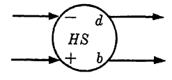
The design of a circuit for subtraction is very similar to the problem of design for addition. The differences are primarily that the inputs must be distinguished as to order and, instead of a carry signal, it is necessary to indicate a borrow signal. Table 1-1 indicates the operation which must be performed by a circuit element we will term a half subtracter. The symbolic notation to be used in circuit diagrams is given in Fig. 1-1. We must distinguish between the two inputs. The plus sign will denote the minuend digit, and the minus sign will denote the digit from the subtrahend. The outputs will show the difference digit and the borrow digit.
TABLE 1-1
SUBTRACTION OF BINARY NUMBERS


FIG. 1-1. Symbolic notation for a half subtracter.
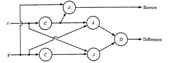
To design a half subtracter, we note by consulting Table 1-1 that the function representing the difference output is given by d = xy' + x'y if x and y represent the two inputs. The order of the inputs is immaterial for the difference output, but to determine the borrow output an order must be stated. We will specify x as minuend digit and y as subtrahend digit. Then the borrow output is given by b = x'y. From these functions, the half subtracter can be designed immediately, as shown in Fig. 1-1.
Note that the circuit for the difference in a half subtracter is identical to the circuit for the sum in a half adder.
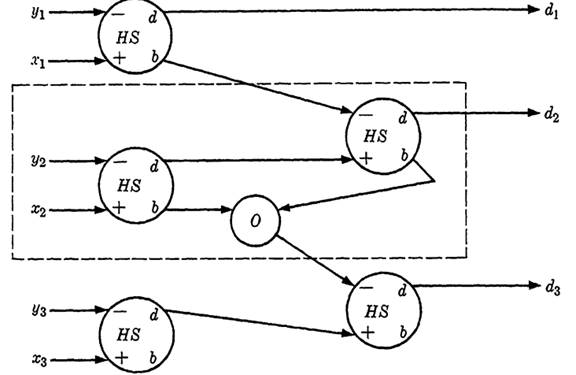
Now, using the half subtracter and the "or" element just as was done in the preceding section on addition, a logical circuit can be designed which will subtract two binary numbers. We will let the minuend be a 3-digit number X = x3x2x1. (The restriction to three digits is only for simplicity of illustration. Any number of digits can be handled in the same way.) The subtrahend Y = y3,y2,y1 will be a number of not more than three digits, which we will assume does not exceed the minuend in size. The difference of the two digits is given as the number D = d3d2d1, represented by the outputs of the circuit.

FIG. 1-1. Logical circuit for a half subtracter.

FIG. 1-2. Circuit for the subtraction of two 3-digit numbers.
sented by the outputs of the circuit. The diagram is given in Fig. 1-2. The unit which combines the second digits is the typical unit. This part of the circuit is enclosed in a broken line. If larger numbers are to be combined, this portion of the diagram is repeated for all number positions except the first and last, which are modified as in the diagram for 3-digit numbers.
 الاكثر قراءة في الجبر البولياني
 اخر الاخبار
اخبار العتبة العباسية المقدسة

الآخبار الصحية


 قسم الشؤون الفكرية يصدر كتاباً يوثق تاريخ السدانة في العتبة العباسية المقدسة
 "المهمة".. إصدار قصصي يوثّق القصص الفائزة في مسابقة فتوى الدفاع المقدسة للقصة القصيرة
 (نوافذ).. إصدار أدبي يوثق القصص الفائزة في مسابقة الإمام العسكري (عليه السلام)


