
The Armstrong oscillator
 المؤلف:
Stan Gibilisco
المؤلف:
Stan Gibilisco
 المصدر:
Teach Yourself Electricity and Electronics
المصدر:
Teach Yourself Electricity and Electronics
 الجزء والصفحة:
459
الجزء والصفحة:
459
 16-5-2021
 3261
3261
The Armstrong oscillator
A common-emitter or common-source amplifier can be made to oscillate by coupling the output back to the input through a transformer that reverses the phase of the fed-back signal. The phase at a transformer output can be inverted by reversing the secondary terminals.
The schematic diagram of Fig. 1 shows a common-source amplifier whose drain circuit is coupled to the gate circuit via a transformer. In practice, getting oscillation is easy. If the circuit won’t oscillate with the transformer secondary hooked up one way, you can just switch the wires.
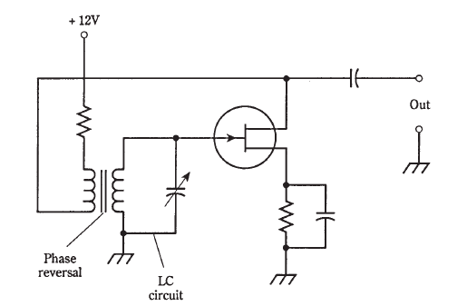
Fig. 1 An Armstrong oscillator.
The frequency of this oscillator is controlled by means of a capacitor across either the primary or the secondary winding of the transformer. The inductance of the winding, along with the capacitance, forms a resonant circuit. The formula for determining the LC resonant frequency. If you’ve forgotten it, now is a good time to review it.
The oscillator of Fig. 1 is known as an Armstrong oscillator. A bipolar transistor can be used in place of the JFET. It would need to be biased, using a resistive voltage- divider network, like a class-A amplifier.
 0
0
 0
0
 الاكثر قراءة في الألكترونيات
 اخر الاخبار
اخبار العتبة العباسية المقدسة


