
x

هدف البحث
بحث في العناوين
بحث في المحتوى
بحث في اسماء الكتب
بحث في اسماء المؤلفين
اختر القسم
موافق

تاريخ الفيزياء
علماء الفيزياء


الفيزياء الكلاسيكية
الميكانيك
الديناميكا الحرارية
الكهربائية والمغناطيسية
الكهربائية
المغناطيسية
الكهرومغناطيسية
علم البصريات
تاريخ علم البصريات
الضوء
مواضيع عامة في علم البصريات
الصوت
الفيزياء الحديثة
النظرية النسبية
النظرية النسبية الخاصة
النظرية النسبية العامة
مواضيع عامة في النظرية النسبية
ميكانيكا الكم
الفيزياء الذرية
الفيزياء الجزيئية
الفيزياء النووية
مواضيع عامة في الفيزياء النووية
النشاط الاشعاعي
فيزياء الحالة الصلبة
الموصلات
أشباه الموصلات
العوازل
مواضيع عامة في الفيزياء الصلبة
فيزياء الجوامد
الليزر
أنواع الليزر
بعض تطبيقات الليزر
مواضيع عامة في الليزر
علم الفلك
تاريخ وعلماء علم الفلك
الثقوب السوداء
المجموعة الشمسية
الشمس
كوكب عطارد
كوكب الزهرة
كوكب الأرض
كوكب المريخ
كوكب المشتري
كوكب زحل
كوكب أورانوس
كوكب نبتون
كوكب بلوتو
القمر
كواكب ومواضيع اخرى
مواضيع عامة في علم الفلك
النجوم
البلازما
الألكترونيات
خواص المادة
الطاقة البديلة
الطاقة الشمسية
مواضيع عامة في الطاقة البديلة
المد والجزر
فيزياء الجسيمات
الفيزياء والعلوم الأخرى
الفيزياء الكيميائية
الفيزياء الرياضية
الفيزياء الهندسية
الفيزياء الحيوية
الحاسوبية
الفيزياء الطبية
طرائق تدريس الفيزياء
الفيزياء العامة
مواضيع عامة في الفيزياء
تجارب فيزيائية
مصطلحات وتعاريف فيزيائية
وحدات القياس الفيزيائية
طرائف الفيزياء
مواضيع اخرى
مخفي الفيزياء

Audio amplification
 المؤلف:
Stan Gibilisco
المؤلف:
Stan Gibilisco
 المصدر:
Teach Yourself Electricity and Electronics
المصدر:
Teach Yourself Electricity and Electronics
 الجزء والصفحة:
448
الجزء والصفحة:
448
 16-5-2021
 1444
1444


Audio amplification
The circuits you’ve seen so far have been general, not application-specific. With capacitors of several microfarads, and when biased for class A, these circuits are representative of audio amplifiers. As with RF amplifiers, there isn’t room enough to go into great depth about audio amplifiers in this book, but a couple of important characteristics deserve mention.
Frequency response
High-fidelity audio amplifiers, of the kind used in music systems, must have more or less constant gain from 20 Hz to 20 kHz. This is a frequency range of 1000: 1. Audio amplifiers for voice communications must work from 300 Hz to 3 kHz, a 10: 1 span of frequencies. In digital communications, audio amplifiers are designed to work over a narrow range of frequencies, sometimes less than 100 Hz wide. Hi-fi amplifiers are usually equipped with resistor-capacitor (RC) networks that tailor the frequency response. These are tone controls, also called bass and treble controls.
The simplest hi-fi amplifiers use a single knob to control the tone. More sophisticated “amps” have separate controls, one for bass and the other for treble. The most advanced hi-fi systems make use of graphic equalizers, having controls that affect the amplifier gain over several different frequency spans.
Gain-versus-frequency curves for three hypothetical audio amplifiers are shown in Fig. 1. At A, a wideband, flat curve is illustrated. This is typical of hi-fi system amplifiers. At B, a voice communications response is shown. At C, a narrowband response curve, typical of audio amplifiers in Morse code or low-speed digital-signal receivers, is illustrated.

Fig. 1: At A, frequency response for music; at B, for voice signals; at C, for narrowband digital signals.
Volume control
Audio amplifier systems usually consist of two or more stages. A stage is one bipolar transistor or FET (or a push-pull combination), plus peripheral resistors and capacitors. Stages are cascaded one after the other to get high gain.
In one of the stages in an audio system, a volume control is used. This control is usually a potentiometer that allows the gain of a stage to be adjusted without affecting its linearity. An example of a simple volume control is shown in Fig. 2.
In this amplifier, the gain through the transistor itself is constant. The ac output signal passes through C1 and appears across R1, a potentiometer. The wiper (indicated by the arrow) of the potentiometer “picks off” more or less of the ac output signal, depending on the position of the control shaft. When the shaft is fully counterclockwise, the arrow is at the bottom of the zig-zaggy line, and none of the signal passes to the output. When the shaft is fully clockwise, the arrow is at the top of the zig-zaggy line, and all of the signal passes to the output. At intermediate positions of the control shaft, various proportions of the full output signal will appear at the output. Capacitor C2 isolates the potentiometer from the dc bias of the following stage.
Volume control is usually done in a stage where the audio power level is quite low. This allows the use of a small potentiometer, rated for perhaps 1 W. If volume control were done at high audio power levels, the potentiometer would need to be able to dissipate large amounts of power, and would be needlessly expensive.
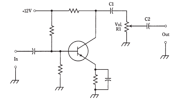
Fig. 2: A simple volume control. Component designators and functions are discussed in the text.


 الطاهرة ركن الإسلام الثالث
 عناوين أم عنوانات؟
 أبنائي الطلبة
 EN
EN